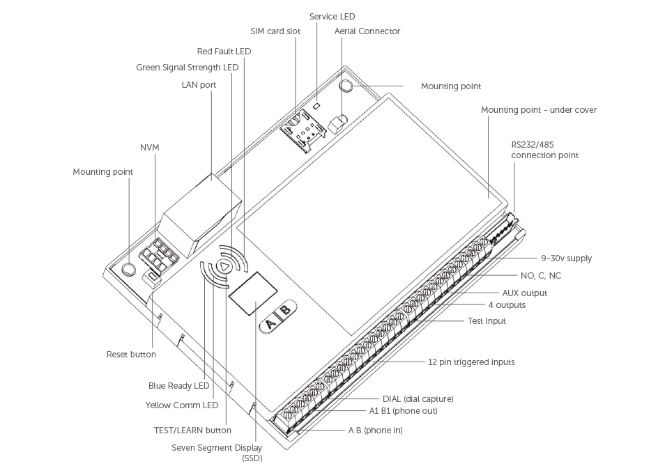
Technical Specifications

| Dimensions | 21 mm (h), 132mm (w), 94mm (d) | ||||||||||||
| Weight | 140g including NVM and SIM | ||||||||||||
| Temperature | -20C to +60C transit, -10C to +50C operating | ||||||||||||
| Humidity | 0 - 80% non - condensing | ||||||||||||
| Mounting |
Any orientation |
||||||||||||
| Warranty | 5 years | ||||||||||||
| Power Requirement | 9.0v - 30.0v | ||||||||||||
| Current Consumption | Quiescent = 20 mA Signalling = 200 mA |
||||||||||||
| LED Indications |
|
||||||||||||
| Radio Path | 2G GSM and 3G GPRS services | ||||||||||||
| Aerial | 50 ohm (nominal) on MMCX socket | ||||||||||||
| Operation Method | Store and Forward (SIA) Pass Through (Fast Format/CID) | ||||||||||||
| CIE Interconnections | Input ‘pin triggering' (Parallel) 12 channels, Analogue (Dial Capture), RS232 Serial, RS485 Bus |
||||||||||||
| RCT Protocols | Fast Format/Contact ID/SIA | ||||||||||||
| Input Terminals | Max +30v, Min 0 Vdc (reference supply 0v terminal) 100k pull-up resistor to +5v |
||||||||||||
| Low Battery | 9.8v falling, 12.0v recovery | ||||||||||||
| Fault Output | Changeover contacts (60v max, 100mA max) | ||||||||||||
| Aux Output | Normally Open contact, may be inverted (60v max, 100mA max) |
||||||||||||
| General Purpose outputs | Four. Each switched to 0v (30v max, 100mA) | ||||||||||||
| User Serviceable Parts | There are no user serviceable parts within the GradeShift | ||||||||||||
| Standards | Suitable for use in alarm systems complying to: EN50136-1:1998 Security Grade 4/DP3 EN50136-2:2012 SP3 (RADIO) SSF 114 v2 Larmklass 2 EN50131-10 Type Y ATS Classification: EN50136 ATS5/SP3 ATS 5 parameters: D3/M3/T4/S2/I3/A3 |
||||||||||||
| Environmental | EN50136/EN50131 Environmental class II Device should not come into contact with water |
||||||||||||
| Emissions | EN55022 | ||||||||||||
| Installation | The CS5301-01 shall be installed by a service person and be powered by a Limited Power Source in accordance with clause 2.5 of EN 60950-1 or equivalent, not exceeding the maximum voltage of 30 Vdc, capable of delivering a minimum current of 200mA and be current limited (fused) to 1A. It shall be installed inside an enclosure of another I&HAS component which shall be that of a CIE conforming to EN 50131-3, or a PSU conforming to EN 50131-6. |
Figure 2 - LED Indications
| LED LABEL | DESCRIPTION |
LED STATUS |
|||
|
ON |
FLASHING |
OFF |
OTHER |
||
| Green | GPRS Signal Strength | Strong Signal Strength | Acceptable Signal Strength | Low Signal Strength, not acceptable | LED off and Red Fault LED on indicates no signal |
| Yellow | Communications | Input is triggered or Dial Capture is in progress | Sending a message to Gemini and ARC | No communication is in progress | Rapidly flashes to show successful communication |
| Red | Fault | Fault present see troubleshooting section | NVM contains factory defaults | No faults exist | On for 2 seconds indicates communication failure |
| Blue |
Ready |
Unit is ready to send messages to Gemini and ARC |
N/A |
Unit is busy and not ready to send new messages |
LED off and Red Fault LED on indicates programming file is yet to be downloaded (usually takes 5-8 mins from power up with good signal) |
| Service (SVC) (next to aerial socket) | Network Status | N/A |
SIM card registered on network |
There is insufficient power or no power connected to the DualCom |
Rapid flashing indicates unit is not registered to network |
