Panel Connection – Ethernet Module
| Manufacturer | Honeywell |
| Model | Galaxy |
| Version | Dimension, G3, Classic |
| Minimum Panel Firmware | V4.5 Minimum |
| Cable required? | Provided with DualCom Pro |
| Panel Profile |
Honeywell-Galaxy-Eth-RS485 |
| Panel Bus Connection | RS485 |
| Technical Notes | N/A |
Panel Connection Information
| Manufacturer | Panel | Connection | Cable/Plug On | Supplied Cables |
| Honeywell | Galaxy Classic/G3 Dimension | Ethernet Module | Lead provided with DualCom Pro or normal alarm cable | Green – RTN Blue – RS485 B Red – RS485 A |
Connection and Power Up.
- Place the Galaxy panel in engineer mode.
- Connect the aerial(s) provided to the DualCom Pro.
- Connect power to the DualCom using AUX supply from the panel.
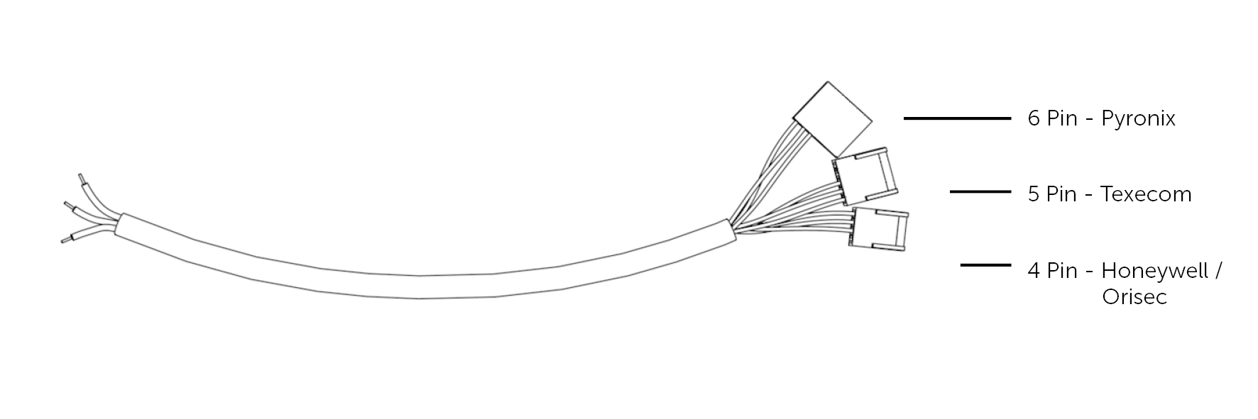
- Connect the DualCom Pro directly to the Galaxy’s 485 bus using the lead provided. (4pin connection for panel – 3 wires A,B,RTN(-) for Pro) Note this must be bus line 1 of the Galaxy panel.
- The DualCom Pro will go through its power-up/registration process which will take approximately 2-3 minutes. The unit will reboot once completed. (Display will show N – C – R then reboot)
- Once the reboot has completed go to CSL My Base and change the panel type on the device to ‘Honeywell-Galaxy-Eth-RS485’
Panel programming
- Enter panel programming (12345 or 1234 Default code)
- Select option 48
- Select option 1 (system access).
- (48.1.1) Select option 1 (Engineer).
- Esc all the way out.
- Enter engineer mode (112233 or 1122 Default code)
- Select option 56 (communication).
- Select option 4 (Ethernet).
- Select option 02 = Alarm Reporting.
- (56.4.2.1) Select option 1 = Format
- Select option 1 = SIA
- Select SIA level 3
- Activate/deactivate any alarm groups you require (As default: 08 = Omit, 10 = setting, 13 electrical status are all turned OFF).
- Esc back to 1=Format
- Go across to option 2=Primary IP Ent
- (56.4.2.2.1) Select option 1=IP address (Set this to 127.0.0.1 – 127.0.0.9) press Ent
- (56.4.2.2.2) Select option 2=Port no. (set this to 50561)
- Esc back to option 2 = primary IP
- Go across to option 4 = Account no.
- (56.4.2.4) Enter the last 6 digits of the Connection ID found on M Base.
- Esc back to 02 = Alarm Reporting
- Go across to 03 = Remote access
- (56.4.3.1) Enter 1 = Access period make sure it’s set to Anytime. Esc back
- (56.4.3.2) Go across to 2 = Mode. Make sure it’s set to Direct Access.
Escape all the way out of engineer mode, this will then learn the DualCom on the bus line and will add 2 modules. Com Mod 4 and RKP 15
Programming complete.
Trouble shooting and testing
You can see if the unit is already learnt on the bus line by going into:
61 – diagnostics / 1=latest / 02=KEYPAD COMMS / keypad 15 = 100%
61 – Diagnostics / 1=latest / 06=COMMS MODELS / ETHERNET 100%
You can check to make sure the Dualcom had taken the Panel type:
- Press the A button on the pro unit until R is displayed.
- Press C. The display should read GALAXY UNKNOWN.
- If the display reads NONE please call our Tech support.


